

A set of goals were set to drive the project. Features that adhere to these goals were then agreed upon.
Controller:
Bag:
Head-up Display:
Software:
The controller should allow the user to access his/her laptop with one hand and without the user having to look at the device. A device with a keyboard interface would not conform to the stated goals. A limited set of buttons should be used to trigger commonly used tasks. The device can be connected to the laptop via the Human Interface Device (HID) connection profile so that the controller will be recognized as a keyboard. The concept, shown below, mimics the form of a key fob and can be easily carried and stored.

The device will have the following functionality:


I know absolutely nobody is thinking about traveling right now. But I did find some useful information about the size limitation of Lithium Ion batteries allowed on airplanes. This limitation is going to be very important to our product, as we want to maximize the spare batteries, but still make the focus and meet the set overall objective of making this system mobile while enhancing productivity. Here is what the TSA says: "Lithium ion (rechargeable) batteries are limited to a rating of 100 watt hours (Wh) per battery. These limits allow for nearly all types of lithium batteries used by the average person in their electronic devices. With airline approval, passengers may also carry up to two spare larger lithium ion batteries (101-160 watt hours). This size covers the larger after-market extended-life laptop computer batteries and some larger batteries used in professional audio/visualequipment." And if you make some phone calls they will tell you it is still at the discretion of the TS gate agent, and prior permission is strongly suggested. We would very much like this system to be TSA approved, and I believe it is very possible to accomplish that.
I have been researching push button switches, and have spent more time than I want to mention looking at different types of button that might be useful for our keyfob controller design. One difficult element of the controller to solve are the sideways facing buttons, and how we might accomplish this task with the resources we have available to us in this Covid-19 distanced learning experience. From spending hours looking at possible buttons to use on Digi-Key, or making the trip to skycraft to look at available buttons, and getting lost in their entire selection of products, I don't feel like we have landed on a solid solution yet. Here are some images of button I purchased to work with and see how I like them. Then I had the idea that the controller could be made on pref board, or the prototyping sheild that is available for the Adafruit Feather Microcontroller.


Below is a button array on a KeyFob design for a vehicle that could be useful as a starting point in the controller design. It was found on digikey, but the price is a bit expensive, but it would reduce the amount of 3D printing we would have to.

The vufine wearable display was disassembled to reduce the internal volume needed for the headset. A lot of care was taken in removing the display ribbon cable because an adhesive was used to adhere it to the outer case.

The battery was then disconnected from the device. The power terminals on the PCB was surrounded by small surface mounted elements so it was decided that soldering directly to the board should be avoided. Hence, the battery was removed by cutting its positive and negative wires and longer wires were connected to the previous battery wires. The initial lithium polymer battery had a nominal voltage of 3.7 V and has a capacity of 300 mAh.

Batteries of this type usually have a voltage range of 3.3 V when discharged to 4.2 V when fully charged. When 3.3 V was applied to the vufine PCB, the device activated. However, when a video signal was sent to the device, the extra current draw needed caused the device to deactivate. Applying from 3.6 V to 5 V to the device alleviated that problem.
Below is a quick demo video for a small little project I did for research and the experience while waiting for parts to arrive. Its a Mega 2560 connected to the Temperature Humidity Sensor (DHT11), 16x2 LCD and a Real Time Clock (DS3231). The use of the Mega is overkill but it is what I had from components I had bought previously for other projects.
This Microcontroller will be kept running for temperature comparisons and reliability of the OmniTrek cooling system during the development and testing phases.

The vufine PCB does not have an output terminal to indicate that the device is currently on. This posses a problem because the different headset components need to be integrated to allow all the components to be turned on/off with one button press.

The vufine board has a push button that controls the functionality of the device. When the device is off, the button will turn on the device with when pressed. When the button is pressed while the board is active, the display mode is altered. When the button is depressed for approximately 2 seconds, thedevice turns off.
Because of the multifunctionality of the input,the other components cannot be turned on simply by being triggered by a button press. It was then decided to trigger the on/off state of the other components by monitoring the current draw of the input terminal of the vufine board. This current draw would trigger the two other PCBs, the headset and wireless display, to activate. Discussions with Professor Cara presented two solutions to this problem. An octocoupler can be used to trigger another circuit indirectly.An op-amp may also be used in conjunction with a resistor to trigger a transistor to switch on, connecting the other components to ground.
This post is dedicated to the power supplies that had to be made to be able to breadboard and prototype the circuits that are planned. We need a 5V power supply and a 12V power supply for the cooling system assembly. The fans both need 12V that will be supplied by the battery bank, the voltage divider circuit will need 5V that can be supplied from the microcontroller. Although for testing purposes and troubleshooting I have made a 5V power supply from an old USB charger by finding the +/- pins and extendeding those to reach the breadboard pins. Below is a photo of the end result, and how it looks in a breadboard.


To construct a 12V power supply for the fans I need to order the battery bank that we had found. I've put off the purchase a little bit because it is an expensive item, and still wanted to make the best possible choice. The battery bank choosen is especially nice because it has several features, if we had to make our own, I feel like we would have included. It has a dedicated 12V output, 2 USBs output, and then the best part is the AC outlet, making this very vestile and able to charge all type of laptops, and or USB devices.

The battery bank came with a 12V cigerette lighter adaptor. I decided to hack into this a create the connections I need for a fan power supply.


Now taken apart. I like the indicator LED and would like to keep it, and seeing the fuse got me thinking about safety, and how might I include a fuse for the fan system.
Moving forward I made the solder connection and used heatsink to take some stress offf the solder joints. Getting it all back into the plastic casing wasn't necessary but it looks nice for the tie being. I will need to re evaluate this cable before the final installation, make sure the lengths are appropriate and it is not unnecessarily big.


Plugging it in and seeing the indicator light was a good sign. The next and final step was to power up the fans directly by inserting the stripped hot and ground wires into the fan cable terminal.


Thermistor Reseach
Thermistors are temperature sensitive resistors. There are Negative Temperature Coefficients (NTC) where when temperature increases the resistance will decrease and then Positive Temperature Cofficients (PTC) termistors, where resistance increases with temperature. We will be using the more common NTC type for this type of application. Worth noting is that PTC thermistors can be useful to choke back current and protect a circuit, when it heats up. Here are a couple different kinds of thermistors. The epoxy coated one is the choosen component for the project, and purchased from Adafruit, it was four dollars. The picture with three componenets are the ones purchased from Skycraft, they were about fifty to seventy-five cents a piece. The epoxy coated thermistor is water proof, and could be used in some extreme conditions.


To use a thermistor you need to convert a resistance to a temperature. Usually thermistors change is around 100 Ohms per degree Kelvin.
Since we will be using a microcontroller, and it's available analog to digital converter, which can only read voltage levels. We will need to convert a voltage reading to a resistance value first.
To do this we will need to create a simple voltage divider circuit, and the thermistor chosen came with a 10k Ohm resistor with a tolerance of 1% for this purpose. The thermistor choosen from Adafruit also came with a datasheet that gives detailed resistances and their coorelating temperatures.
The Steinhart-Hart Equation is used. It requires you to have three different temperature and resistance data pairs to solve a system of equations. Below is the details of the Steinhart-Hart equation.

The response of the thermistor is not linear, but it is predictable since the equations are modeled with the natural log. Below is the output of an online Steinhart-Hart calculator, where the curve can be seen. The solved coefficients are also displayed.

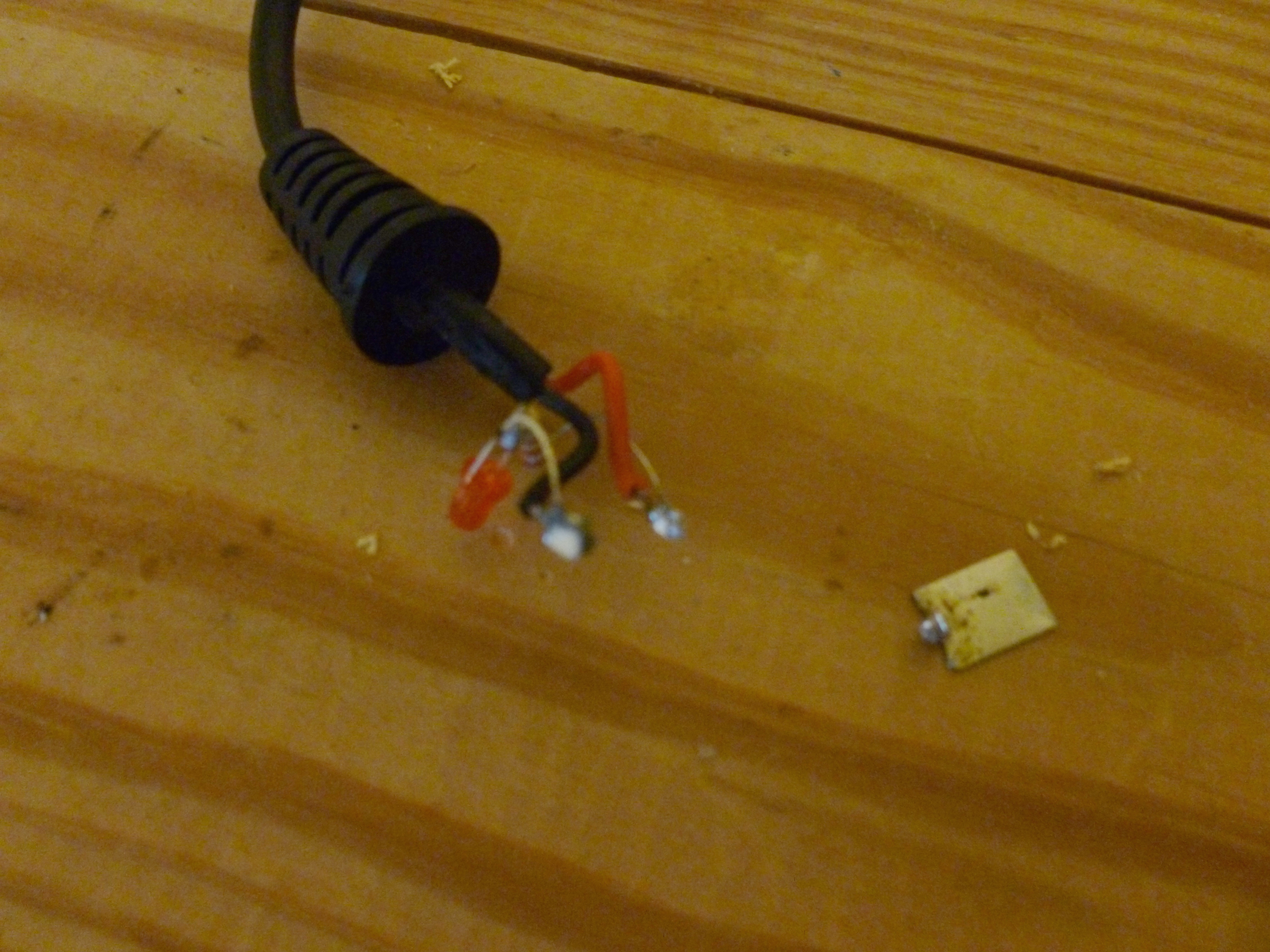
The outer plastic shell for the Mirascreen device was removed, leaving behind two PCBs.

There are two PCBs associated with the Miracast functionality. The smaller PCB with the antenna is responsible for communication via a direct Wi-Fi network. The larger PCB processes the signal and produces a video output via its HDMI port. The larger PCB also powers both boards when 5 V is applied to its micro USB port.
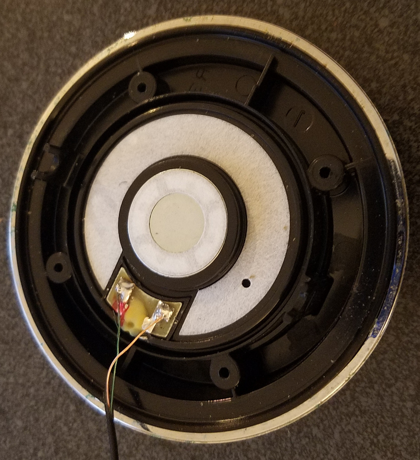
The speakers from an old surrogate headphone set were used as audio outputs for the Bluetooth amplifier board.
The circuit used to turn on both the Mirascreen and the Bluetooth Amplifier boards when the Display PCB is drawing current is shown below. A sensor resistor is used to provide a differential voltage for an op amp when a current is applied to it. The op amp will then activate a NPN transistor which will supply ground to both the Mirascreen and Bluetooth boards. The sensor resistor will result in a voltage drop. This means that the Display board will not receive the full 5 volts from the source. The size of the resistor should not be large enough to drop the voltage below the tolerance of the board.


The previous schematic to turn on all the components of the headset when the display module was engaged worked as expected until an HDMI cable connects the Mirascreen to the display module. When the connection occurs,the Mirascreen would activate regardless of the state of the display module. We surmised that the problem occurs because the connection allows an alternate path to ground for the Mirascreen. If this is true, the transistor will not have an effect because the Mirascreen would always be pulled to ground. The circuit,shown below, was setup to test if this hypothesis was true.


I have been trying to establish communication with the Beetle microcontroller but I can not even get my computer to register that a device has been plugged in. I do not want to give up on the Beetle but there is little documentations about it, and the troubleshooting tip doesn't sound like something I want to do everytime I upload new code.

A good lesson was learned, and it and it is to check the product reviews out thoroughly before planning with and purchasing the product. There are a couple of good reviews too, so maybe there is a chance I get a working one if I return the one I have. The shipping time wasn't too bad considering it came from China, but I don't see the return going as quickly as I would need it too. Discussing this problem as a group and it had been decided to select another readily available microcontroller that is close in size, and the Arduino Nano might be a suitable replacement.


With the Nano now selected as the board I am once again making progress. I am reluctant to repurchase the Beetle microcontroller, but I thinnk it would be worth another try to take advantage of the "smallest microcontroller available" on the market.
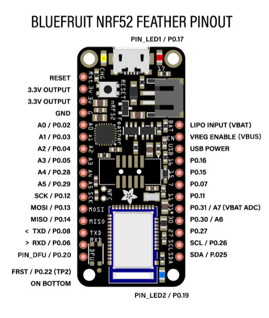
The Bluefruit nRF52 Feather microcontroller will be used for the controller assembly. This Feather is pretty cool in how easy it is to make a Bluetooth device with the Bluefruit LE, which is Adafruit's versioon of Bluetooth Low Energy (BLE) technology. Using the Bluefruit LE Connect application I was able to connect the microcontroller via bluetooth to my iphone or desktop computer and send keyboard commands to any open application that accepted a keyboard input. I will put together a demo video and post it as a learning step that was done, to be able to make the more advanced controller we are intending to make.
This is a diagram of the cooling assembly made in Fritzing.

The next step for the cooling module is to build the circuit on some perf board and attach it to the Nano (which has replaced the Beetle).
This video demo shows the troubleshooting of the PWM to control the speed of the fans.
The next step is to install the fans into the backpack. Some plans have been made for the installation although it is still going to be a challenge to get the fans in the side bottom area of the bag where the mesh features can be used as a filtering device.

A video demo was made for the early stages of the controller assembly. In this video an analog joystick that will be used for the mouse navigation as well as seven buttons have been modeled on an Arduino Nano. At this point the mouse and button inputs are just being verified and printed to the serial screen to visualize the basic inputs.
This step initial step in the controller serves many reasons, even though it is not built on the Adafruit Feather nRF52. It has allowed the process of making the controller to begin even without all the needed parts. This demostration and prototype also gives an approxmate size of the controller, and how making it hand held and as small as possible may prove difficult.
The next step for building the controller is to get this code on the Adafruit Feather microcontroller and have the buttons send a command to a connected Bluetooth device. I don't see this being too difficult and I will start out with some basic commands and/or keyboard inputs, before I code the function that will be specific to our system and navigation. Once I am sending inputs to a connected device, I will then code the indicator Neopixel LED that will read the battery power level and change colors depending on battery life. First it will appear green when full, yellow when less than half power, red when less than one quarter of battery life, and flashing red when less than 5% battery remaning. I should be able to use the available PWM pins to control the LED.
I will post another video when I get the Feather microcontroller programmed and set up with the next steps.
The previous schematic to turn on all the components of the headset when the display module was engaged worked as expected until an HDMI cable connects the Mirascreen to the display module. When the connection occurs,the Mirascreen would activate regardless of the state of the display module. We surmised that the problem occurs because the connection allows an alternate path to ground for the Mirascreen. If this is true, the transistor will not have an effect because the Mirascreen would always be pulled to ground. The circuit,shown below, was setup to test if this hypothesis was true.

With the display module off, and 5.2 V being applied to both modules, the current across the ground terminal of the display module was measured in two states. When there was no connection between the two modules, no current was measured at that point. Conversely, when the HDMI cable connected the two modules, a current of 9 mA was measured.
It was determined that a high-pass switch would alleviate the problem by applying the voltage source to the dependent modules instead of pulling them to ground. If the Mirascreen has access to ground via the HDMI cable, it will not affect its state because it always has access to ground in this configuration. The circuit below was designed and tested.

The load switch, TP2031P, was used as the high-side switching mechanism. The circuit mostly worked; however, a video signal was not being produced by the Mirascreen. It was determined that the selected load switch component did not allow for enough current for the Mirascreen to function properly. The circuit below alleviated the current constraint with a different load switch.

The new load switch component, BTS50055, had a max load current well above our needs (70 A). The load voltage for this component is given by the equation:
Load Voltage = source voltage - input voltage
The input voltage is used to enable/disable the device. The op-amp would produce a voltage when there was a current detected across the sensor resistor. The output signal from the op-amp needed to be inverted so that it produced a voltage level of 0 V when there was a current detected and a voltage level of 5 V when there was no current detected. The inversion was achieved by using an NPN transistor.
This blog post is an update to the backpack installation.
It is worth noting that the specific backpack chosen has become critical to how it is all put together. There were many contraints that stemmed from not being able to make a custom backpack, and a lot of problem solving for the best way to use the bag. From the pocket locations to the fabric used in the backpack it all plays a role in how we have decided to install the systems. As a quick reminder here is a picture of the back pack we have chosen with the plan to use a 15 inch laptop for the system.

The following picture are part of the prep work and problem solving that went into installing the two fans inside the bag where they would be useful, and cooling the laptop as needed.
First the bag was turned inside out, as that seemed like the easiest way to be able to work with the limited space. Then a thick gaff tape was applied to increase the ridgeness of the back pack material, and the pilot holes locations were approximated with the dust covers that will be used.


A wooden spacer was also designed because during the initial fan enclosure build it was seen that on the intake side the dust covers could make contact with the fan blades. Some super glue was added to the white gaff tape to increase the stabilty of the mounting holes and the cutout area. The next step was to remove the center piece of fabric and this was done with great care to not damage the backpack or overcut and risk weakening the intregity of the fan mounts.


Since the cooling system is still being tweak, tested and still transitioning between microcontrollers, one fan was completely installed while the other was left uninstalled. The following is a video demo of the system working.


Above are a couple additonal picture to show the detail of the installation. If time is available it might be nice to learn the 3D printing software and redo the spacer that was created, but over all I am happy how this looks, very clean when the bag is flip back to right side out, as the last picture shows.

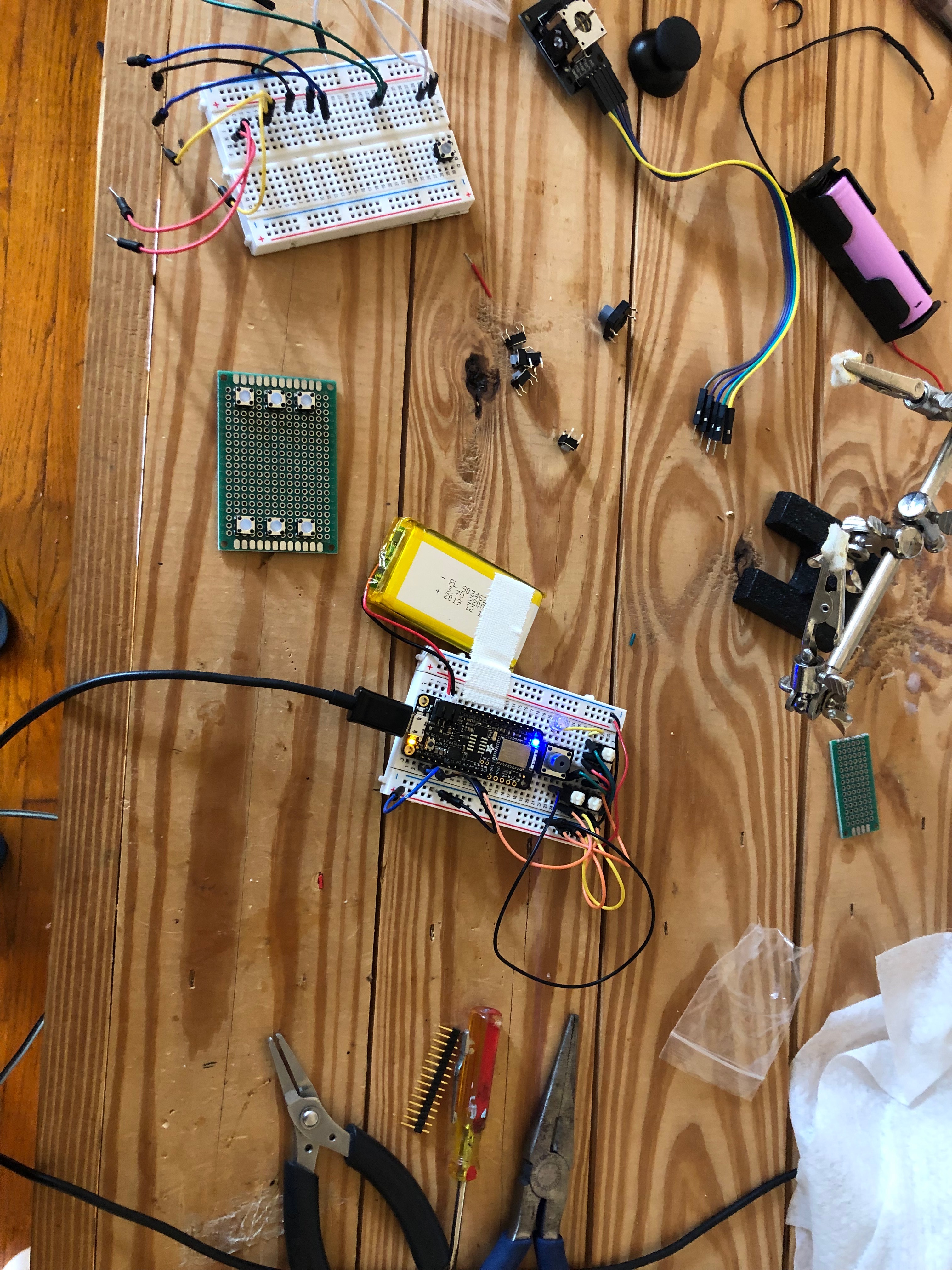
This is a basic diagram for the first version of the controller, this has the X-Y axis joystick, and a total of 8 buttons that will be coded will commands such as Right click, Left click, Volume increase, Volume decrease, Cortana assistance, Menu button, and a lock button. Now that I have the Adafruit Feather and LiPo battery I am able to run the coded microcontroller wirelessly now. The controller is still built on a breadboard so it is not quite a handheld device yet.
Here is an image of the controller in it's early stages now being built on the Feather microcontroller. I have connected the Feather micro controller to my Apple computer and my iphone, and have sent keyboard commands via the serial monitor. In this picture only four buttons are being tested and I am programming them to have a function that will be activated.

The next step is to get the LED working and monitor the battery. The following video is a quick demo of the HID Keyboard function connecting to my desktop computer.
Apple Glasses, another option for a display for the OmniTrek system.
It is pretty cool to be working on a project and you see a company like Apple releasing a product that could be adpated our system. If and when we ever design the OmniTrek mobile computing system for Apple product I would be trilled to utlize something like the Apple Glasses. Reading about what these glasses can do is pretty amazing, and gives our team many ideas for future improvements.
Here is a link where this article was found:
https://appleinsider.com/articles/20/05/19/apple-glass-details-leaked-will-cost-499-and-work-with-prescriptions

The PCB for the headset's switching circuit was designed using the EasyEDA service to generate the Gerber file.


The outer case for the headset, controller, camera, and other various parts were created by using a 3D printer. The 3D printer used was a Monoprice Delta Mini. This printer has a cylindrical build volume of 110 mm in diameter and 110 mm vertical. PLA was used to as the build material. It should be noted that PLA has a very low temperature resistance (60 C), and is not weather resistant. Hence, this prototype cannot be used outdoors.
The components were created using Blender. While Blender is not parametric, and does not have tools specifically tailored for technical 3D printing (like fusion 360), prior familiarity with the software allowed for rapid development of the components.

The relatively small build volume meant that multiple interlocking panels had to be used to enclose the electronics. The blender files were used to print and assemble the following components.

This post is an update to the backpack installation.
A lot of this work has been done over a long period of time, doing little by little as it is figured out. So a lot of this progress is long overdue for a blog posting.
This post is an update to the backpack installation.
A lot of this work has been done over a long period of time, doing little by little as it is figured out. So a lot of this progress is long overdue for a blog posting.
This week I received the new Beetle Microcontroller I ordered. I wasn't too hopeful because the previous purchased Beetle did not comminucate or register when connected on my Windows laptop nor my other computer, a Mac mini. So I was very happy when I tried it out and was able to load the code I already had running and currently being tested on the Nano MC board. Since we have been behind schedule I wasn't planning on going back and trying to get the Beetle to work, but I am glad I did not give up on it, and we can resume the plan of using the Beetle in the final project once again.

In this first Omni-Trek demo video of the thermistor controller fan speed code that is now on a Beetle. A second Beetle was purchased, and the first one will be returnedThe thermistor being used is not the epoxy 10K component we intend on using, that thermistor is currently being used with the Nano and performing tests.
The Steinhart - Hart coefficients need to be calculated for this 1K thermistor, and to do so I need three accurate temperature readings and their correlating resistance value. The 1K thermistor should be measured to be 1K at 25 degrees Celsius. Then, when I have the values, I will find online calculator programs to solve the Steinhart-Hart equation. If you are looking for the equations please go up a couple post where I talk more about thermistors and the equation.
In this next video, I show the process in which resistance data from the 1K Thermistor was gathered over a range of temperatures. Since the use of a DHT11 sensor coded to update every 10 seconds is the source of the temperature measurements it will not be very precise. The range of resistances will have to averaged to determine the three data pairs needs to calculate the Steinhart- Hart coefficients.
Here is the online calculator I used:
https://www.thinksrs.com/downloads/programs/therm%20calc/ntccalibrator/ntccalculator.html
Below is a picture of the 1K measurement on a multimeter when the temperature was 25 degrees Celsius, exactly like it should be.

Update to the Controller.
This post is reporting a change in plans with the controller. We have decided to make a second version, and instead of using physical button we will use a TFT touchscreen interface. Below is picture of the controller design with buttons and it is not quite the sleek keyfob design with had envisioned. Even with the smallest buttons we could find the original concieved design was going to be very difficult to accomplish. This PBC shown below measured 80mm x 58mm x 20mm and that was without the addition of the joystick / thumbstick, battery and 3D printed case, so we thought we could do a smaller design, true to the original intent with a touchscreen.

The touchscreen we have chosen to use was selected for the ease of use with the Adafruit feather microcontroller we already have. Kevin will continue to take over the controller development and programming, as he is a very quick and wizard like. Below is a photo of the item we ordered.

Update to the backpack installation.
This post is reporting an installation situation we are running into where the way we have decided to place the battery inside, across the bottom of the bag inside a plastic container to maximize airflow. Throughout the process we have only really been concerned with the electronic that we intend to make, and didn't have a design or mechanism to maximize the airflow within the bag to the laptop.
The idea of a getting a premade plastic container for the enclosure with opening for the fans to channel the airflow within the bag to the laptop storage area/pocket was thought during the installation process. We are finding out that when we have the laptop power supply plugged in the battery bank, there is not enough room in between the fans. This coupled with that fact that due to COVID-19 the team is not meeting up often enough where testing can be done with the 15 inch laptop as planned. Using my 17 inch laptop is not possible with this backpack because it is not designed for a large laptop with 15.6 inches being the maximum for this backpack.


So at this point we are pretty upset we didn't think of this in the planning process. There are many other option on how to secure the battery inside the bag. Another pocket is a possiblity or standing the battery up on it's end as well, as shown in the picture below. But knowing that the battery will be a source of heat with it's internal power supply switching circuit also with the laptop's power supply switching circuit, both will be generating heat that needs to be cooled and should be within the airflow pathway.


So with the extra time we now have another backpack will be explored. During the planning process a lot of the idea stemmed from the backpack I already used, so that might be a viable choice for the second version of the backpack installation. Below is another bag that was found on Amazon where the laptop conpartment zips fully open which looks like a way good idea for what we are trying to do. Thinking forward to the future problems that might be encountered, securing the laptop where the connections that need to be made are not stress the cables used or the laptop ports.

This post will cover the new design of the controller. The old design used a set of tactile buttons to interface with the docked computer. During the process of implementing this approach, certain problems became evident with the initial design. The controller ended up being larger than expected due to the volume of buttons needed. The controller would also been archaic to use because the functionality of the buttons would have to adapt to the needs of various programs. We decided to implement a touchscreen to alleviate these problems.

The core requirements for the controller was not drastically modified. The increased current draw of the TFT screen warranted the use of a higher-capacity battery. The input module of the controller was modified by replacing most of the buttons and the joystick with the resistive touchscreen. Tactile buttons were reserved for the volume controls because volume manipulation is a common task that should be readily available instead of having to navigate through the UI to access it.


The libraries used to program the device was predominately provided by Adafruit.
The main loop of the program involved the following functions:

The nature of the resistive touchscreen meant that, while is is cheaper than a capacitive touchscreen, it was not going to be as sensitive. This trade-off was acceptable because the device did not require gestures and just had to allow the user to press static UI elements. The UI was designed to have large interaction areas to alleviate accuracy problems. The UI also uses a large font that is easily readable at arm’s length. While a more complicated design for the UI can be achieved by using static images, the amount of time the microcontroller would need to refresh each image would hamper the user experience. Primitive shapes that were provided by the graphics library were used instead to create most of the UI. Smaller images were used to accent the UI by loading them directly into memory from the microSD card when the device starts up.

This Omnitrek demo video show the final 3D printed case for the controller. The trials and errors are shown for multiple iterations needed to successfully finish the case design and printing process.
Overview of the Cooling system before final backpack installation.
This video aims to show the internal container that will house the battery and electronics before the systems final installation. The container also assists in maximizing the effectiveness of the cooling system; getting the airflow across the laptop and heat generating components.
At this point in the process we wish we could have custom made a container to house the fans and electronics,. and even with a holster for the laptop. 3D printing something that large would have been an issue, as we would have needed a very large printer. In the process of building the cooling system finding way to get around 3D printing was a goal, but the premade plastic coontainer used did have their constraints.
Here are a couple picture of the plastic container and how it was formed to use in the installation. A lot of different plastic container were exaimed before this particular one was found, and it turned out to be the cheapest also because I found it at Home Depot for $1.88. The smaller container that was to be used for the first backpack was approx. $30 for a set of four from amazon.


And then here is the plastic container in it's final form. The attached lid flaps were added to give the structure some stability where the backpack storage pocket can still be used, they can bare some weight when they are resting on the top of the fans.


Next are the picture of the Beetle microcontroller with the voltage divider circuit attached on a peice of cut pref board. The circuit, as it is detailed above, is fairly simple. It is a thermistor connected to the 5V, and it's other lead connected to a 10K resistor. It is at this connection where the ADC of the Beetle MC can process the temperature from the voltage at the sensor pin. The other lead of the resistor is grounded.
Also shown in the last couple picture here is the shortening of the power supply cable, which no longer has an indictor light, and has been shortened numerous times so far. The connections being made at the Y-splitter cable that feeds both fans the 12V, ground, and the PWM signal coming from the Beetle MC.


And finally here is what the completed system looks like before installation. It's going to be hidden in the bottom of the bag so the functionality is more important that how it looks. All the wires and connections will get heatsink to be easily managed during install and any needed reinstallation.

Update to the backpack installation
This post is an update to the new backpack installation. Having already done the fan installation before on the previous bag, we had a plan already established, and even some improvements for the second backpack. The backpack was turned inside out again and gaff tape and some gorilla glue were added to make the fabric a little more durable and ridged. The fan opening was cut, and the fans fastened in place. The threads shown in the last picture were added so we could visualize the air flow for demostration and testing purposes.


The next two pictures show both fans installed looking down into the backpack. Then a picture of the plastic container installed around the fans.


External Hub update
The external hub very much needs a post and to be talked about alittle bit. Planning for this feature was always a wait and see situation, as far as placement and the design of the Hub. With the first backpack it had a build it exterior USB port, that we planned to use for the camera conection. So, firstly we needed to remove the USB port from backpack#1 and add that feature to the new backpack. This process was straight forward, the opening was traced on to the bag and cut out, while the USB port was super glued in place. It works fine and as expected.


Next are the pictures of the completed External Hub. It has two USB ports that connect to the battery bank, and it also has an HDMI port that is connected to the laptop for screen sharing or a secondary display. Both cables we bought were premade, as making the cables ourselves would have roughly cost the same. Saving the trouble having to solder the connection to terminals as well.


The USB cable was run through the bottom of the bag to battery bank, and the HDMI cable under the plastic enclosure, similar to the thermristor to be accessible in the laptop sleeve. The picture below shows the connections to the battery bank, and you also see the HDMI cable through the container and through the laptop air vent.

This post will cover the first design and 3D print of the headset.
This Omnitrek video update shows the first completed 3d printed headset. After some testing and trials it was decided that a better design will be needed to easily see the display while in motion. The small size of the display was a known challenage to overcome since the early meetings when the Vufine was first recieved and used.
Another update will be available soon with the second version of the headset, where stability is enhanced while the user is in motion.
Final Backpack installation
This Omnitrek video update shows the completed backpack. The External USB/HDMI Hub, and external USB camera Hub are shown, as well as inside the bag where connections are made to the battery bank, and the fan air flow container used to house the electronics and optimize the cooling system. Some features of the bag are hard to show in a video so below will be some more pictures showing some more detail.
Next are some more picture showing the backpack from the front and back, and down inside to where the battery bank and electronics are housed.


This last video is a follow up to show one more feature of the backpack. In the front zipper pocket the AC plug to recharge the battery is accessible.
The following is a demostration video shows a broad overview of the major peices of the Omni-Trek mobile computing system.
This Omni-Trek video update was made in a group meeting once we had finished indivdual assemblies. A couple problems were encountered while doing this demo, which was supposed to be more depth showing the system and components all working together, so more indivdual demostrations are planned.
More in depth demostration videos will be available showing detailed functionality. For example, a feature not shown in this video is the backpack conveniently contains the AC apdaptor in the front zipper pocket for when the internal battery bank needs to be recharged.
This is a demo video showing the controller and headset interacting with a laptop. While the laptop is not currently docked within the bag, the features pertinent to the integration of the system's software is demoed.